Zero applied DC bias does not ensure low distortion
A symmetric AC signal still exercises the nonlinear response of an X7R capacitor. Check the actual AC voltage across the part before accepting it in a precision signal path.
HighSNR Lab · Application Note AN-002 · Rev A
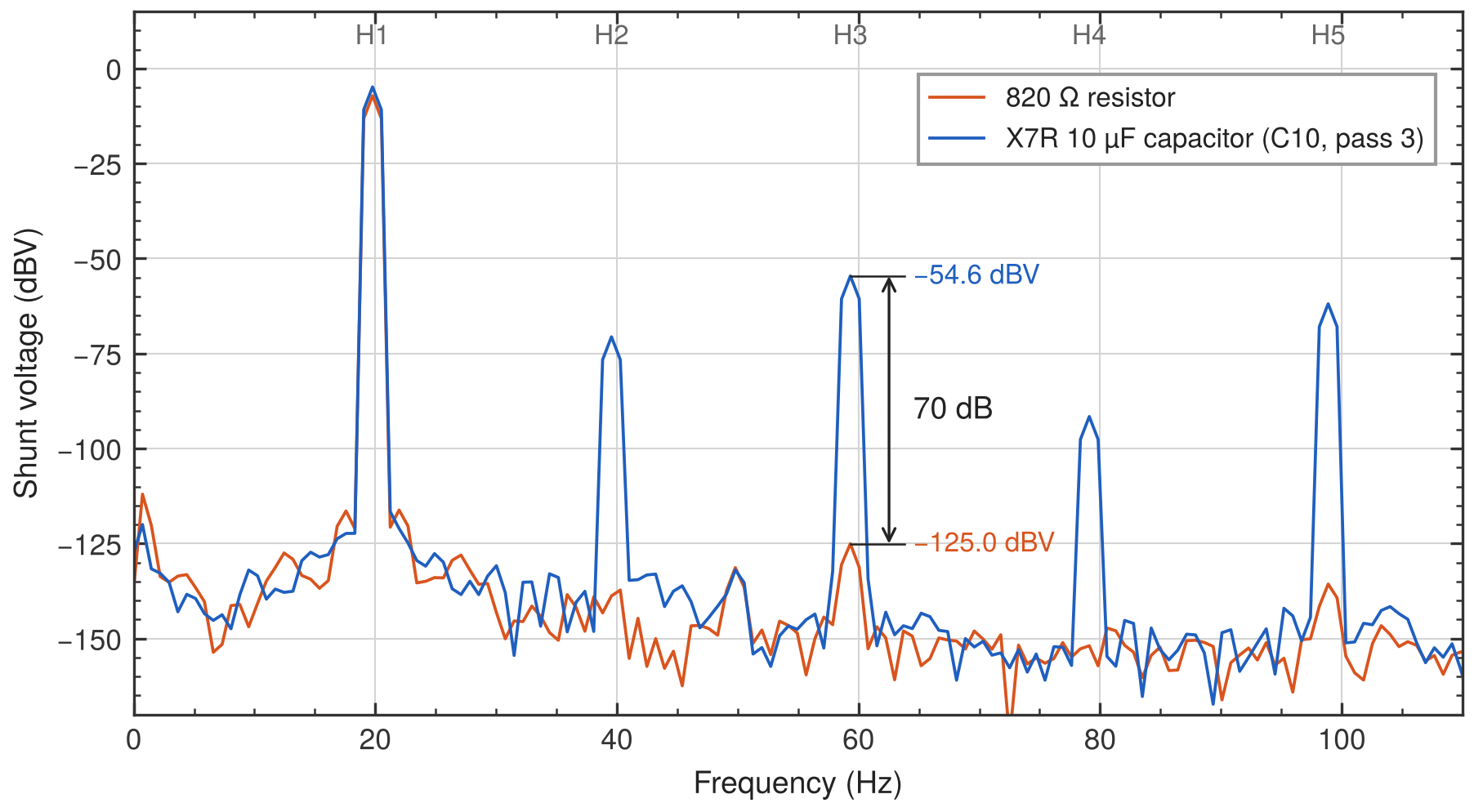
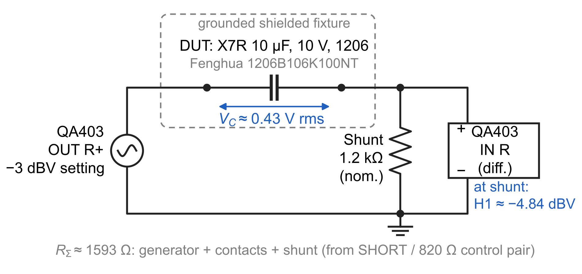
No intentional DC bias. Approximately 0.43 V RMS across the capacitor. Calculated voltage H3: 0.59%.
A measured example for analog designers using Class II ceramic capacitors in RC filters and AC-coupling networks, with a circuit model and a procedure for testing another component.
Engineering takeaways
A symmetric AC signal still exercises the nonlinear response of an X7R capacitor. Check the actual AC voltage across the part before accepting it in a precision signal path.
The measured current H3 is −49.8 dBc. With the surrounding impedances included, the calculated voltage H3 across the capacitor is −44.6 dBc, or 0.59%.
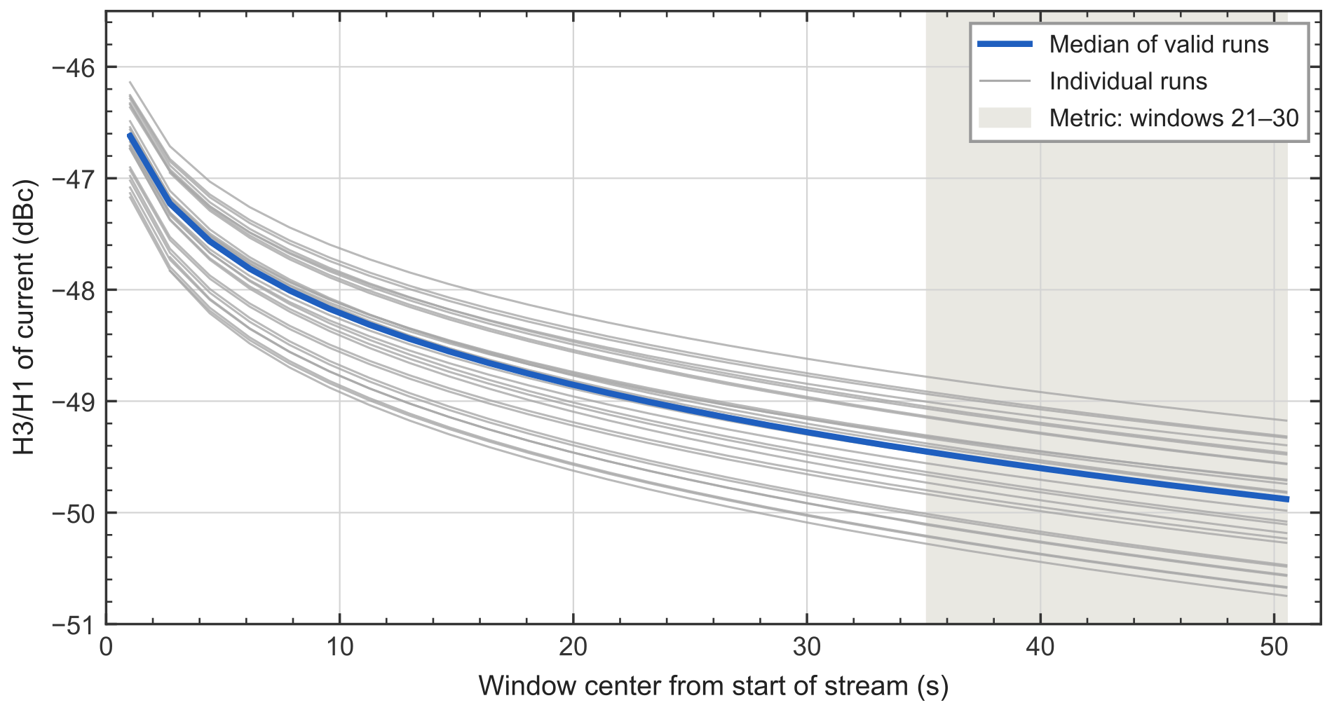
H3 falls by roughly 3 dB during the record. Specify the off interval and analysis interval when comparing parts; the late-record metric is not a demonstrated steady-state value.
Measured distortion
The QA403 drives the capacitor and a sense resistor in series. The voltage across the resistor measures current. Across 29 complete capacitor runs, the mean current H3/H1 is −49.75 dBc.
Repeated parts and mountings
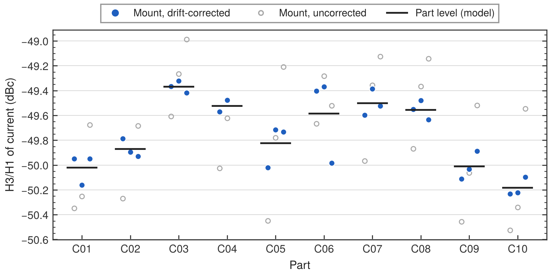
Individual capacitor means range from −50.1 to −49.3 dBc. Each part was removed and reinstalled between passes, with randomized order and bracketing controls.
These measurements cover one tape and one operating point. The observed spread is not a production limit. One incomplete ADC record is preserved in the archive and excluded from the primary statistics.
Excitation history
The first valid windows have a median current H3/H1 of approximately −46.6 dBc. The late-record metric is approximately −49.8 dBc, and H3 is still decreasing near the end of the record.
Each run follows 180 s with excitation off. The reported comparison interval is approximately 35–51 s after excitation begins.
The decay mechanism was not established. The main series did not include amplitude or frequency sweeps, and absolute DC voltage was not independently verified after the acquisition method changed.
From measurement to design
At this operating point, the ratio of total series resistance to capacitive reactance is approximately 1.80. The calculated capacitor-voltage H3/H1 is therefore about 5.1 dB higher than the measured current ratio: −44.6 dBc, or 0.59%.
The full note develops an equivalent harmonic-source model and applies it to a low-pass filter and an AC-coupling network.
The circuit examples are model-based estimates. Transfer to another circuit was not experimentally validated; use comparable capacitor voltage, frequency, bias, temperature, and excitation history.
Open release package
Independent engineering review
HighSNR Lab reviews component operating points, measurement assumptions, and distortion risk in precision analog signal paths.